Important: The Universal Fan Coil thermostat must be installed by a trained technician. Failure to follow these instructions carefully may result in damage to your fan coil.
Caution: Electrical hazard. Equipment and wiring can cause electrical shock and equipment damage. Disconnect power before starting installation.
On This Page
Materials and Tools Needed
Installing the Universe Thermostat
How to Use Your Universe Thermostat Setting System Mode
Materials and Tools Needed
Before installing your new thermostat, you will need:
-
- Screws and drywall anchors (provided with thermostat)
-
- Screwdriver
-
- Bubble level
Mounting The Universe Thermostat
-
- Remove the contents from the box.
-
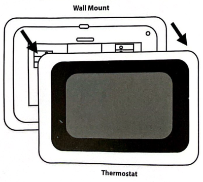
- Detach the wall plate from the thermostat by pulling the two pieces apart.
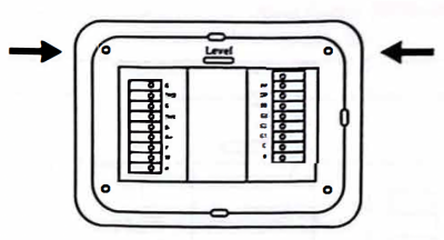
3. Using the level bubble, level the wall plate on the wall.
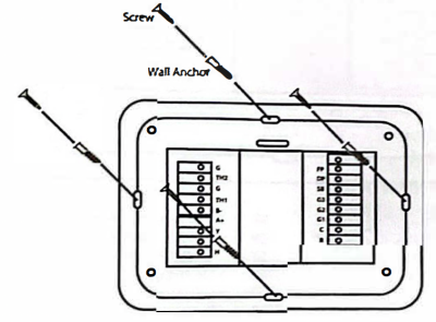
4. Secure the wall plate to the wall with the provided plugs and screws (ensure up arrows are pointing up).
5. With the wall plate firmly mounted on the wall, make your wiring connections using the following table as a guide:
| System Type | Wiring Connections |
| Heat Pump (O/B Selection) |
R-24VAC * For equipment calling for compressor or reversing valve. If used for Unilux heat pumps, ensure control board dipswitch #1 is set to “On.” |
| Heat Pump (W Selection) |
•R-24VAC * Default setup for Unilux heat pump equipment and hybrid heat pumps. |
| 4-Pipe Vertical Fan Coil | R – 24VAC Y – Call for Cool W – Call for Heat G1 – Fan Low G2 – Fan Medium G3 – Fan High C – Common Power |
| 2-Pipe Vertical Fan | R – 24VAC W – Call for Heat/Cool G1 -Fan Low G2 -Fan Medium G3-Fan High C -Common Power G – Water Pipe Temperature Sensor TH2 – Water Pipe Temperature Sensor |
| 2-Pipe Vertical Fan Coil with Auxiliary Heater | R – 24VAC Y – Auxiliary Heat W – Call for Heat/Cool G1 – Fan Low G2 – Fan Medium G3 – Fan High C – Common Power G – Water Pipe Temperature Sensor TH2 – Water Pipe Temperature Sensor |
| 2-Pipe Vertical Fan Coil with Aquastat | R – 24VAC Y – Call for Cool W -Call for Heat G1 – Fan Low G2 – Fan Medium G3 – Fan High C – Common Power |
| General Connections | Data Connections – B- & A+ for R15 Board or BACnet Freeze Protection Sensor – FP trigger signal (Input +24VAC) Drain Pan Overflow Sensor – DP trigger signal (Input +24VAC) Setback Contacts/Sensor – SB trigger signal (Input +24VAC) Humidifier – H trigger signal (output +24VAC) |
6. Mount the thermostat body to the back plate by gently pushing the body onto the wall plate (ensure up arrows are pointing up).

Setting System Mode
-
- If wired correctly, your thermostat should now power on when turning on your HVAC system.
-
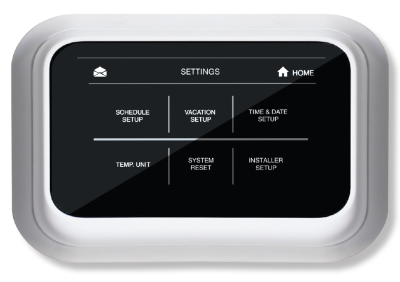
- From the home screen, select the gear icon on the top right corner of the screen to access the settings menu.
3. Press and hold installer setup on the bottom right corner of the screen
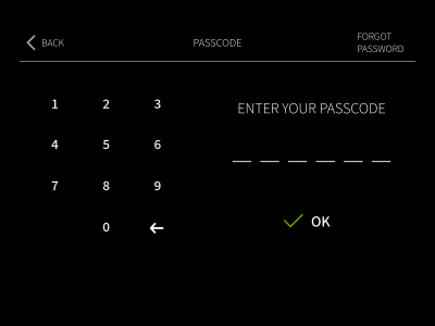
4. Enter the default passcode – 123456. Press okay.
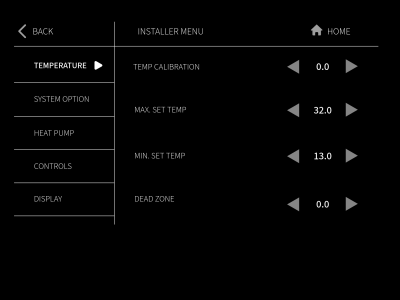
5. In the Temperature field, set:
a. Temperature calibration
b. Set maximum temperature
c. Set minimum temperature
d. Set temperature dead zone
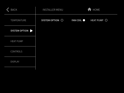
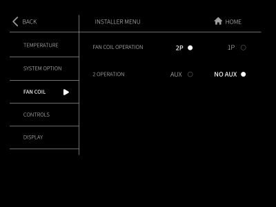
6. In the System Option field, select the type of equipment, either fan coil or heat pump.
a. If fan coil is selected, the lefthand menu will populate with fan coil settings.
b. Enter the menu and select the type of fan coil: 2-Pipe system or 4-Pipe System.
c. If using a 2-Pipe system, select Aux if the unit is equipped with an auxiliary heater. If there is no auxiliary heater, select “No AUX.”
Note: If the fan coil is equipped with an aquastat you must select “4P”, even if you are connecting a 2-pipe fan coil.
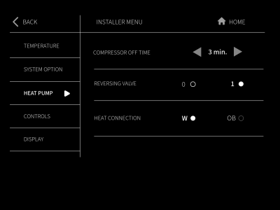
d. If heat pump is selected, the lefthand menu will populate with heat pump settings.
e. Enter the menu and set the following settings:
-
- Compressor Off Time (for retrofit applications)
-
- Reversing Valve – Activate In heat (0) or activate In cool (1)
-
- Heat Connection – W or O/B
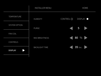
7. In the Display menu, set:
a. Humidity- control or display (your thermostat can only control humidity if there is a humidifier built into your HVAC system)
b. Purge time – we recommend setting to 5 minutes.
c. Maximum Brightness
d. Backlight Time
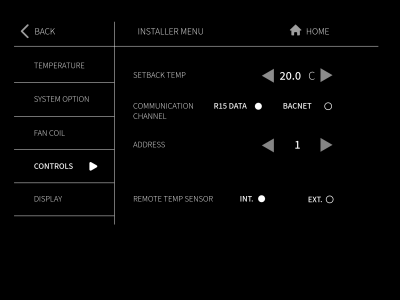
8. In the Controls menu, set:
a. Setback Temperature
b. Communication Channel – R15 or BACnet.
Note: If BACnet is selected, be sure to give your thermostat a unique thermostat address number that has not been used in the building.