

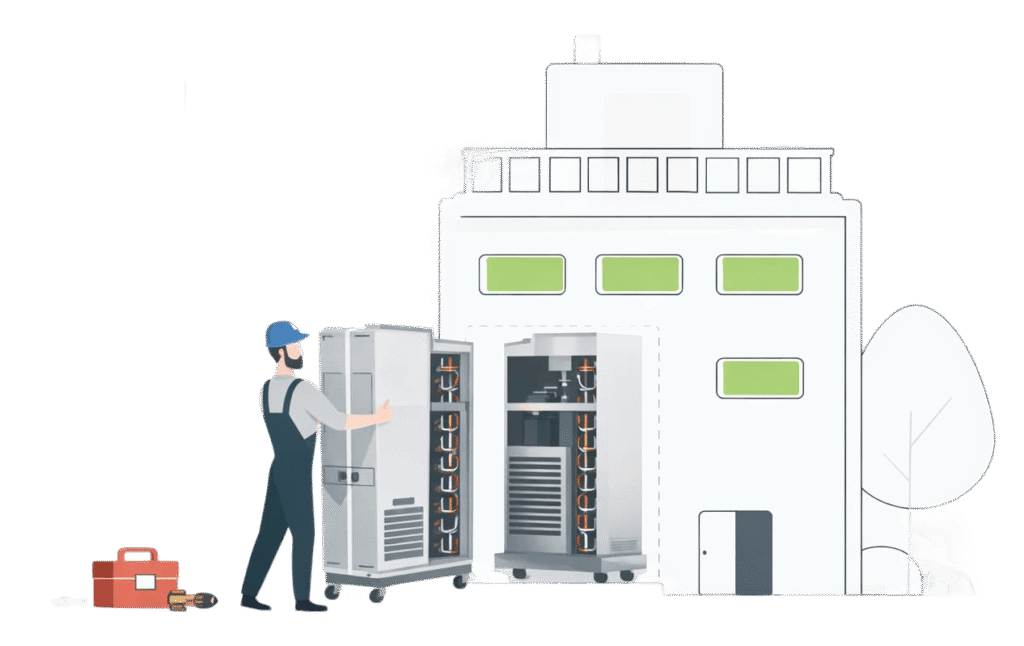
VI Series Heat Pump Chassis - Version 1, 2, 3, 4
OEM Replacement Chassis
- Cooling only
- Heating only
- Low sound level
- Fast and easy replacement
- Damage protection
The Whalen VI series Version 1,2,3,4 replacement chassis is designed for Whalen VI units produced between 1993 to present. They are available in 200, 300, 400, 500, 600, 800, 1000 and 1200 capacities. As part of a complete system, the Whalen VI Series Version 1,2,3,4 unit is engineered to fit into the existing cabinet space with matching electrical/water connections as the original unit.
Each unit utilizes energy efficient quality components and tested in our psychrometric room to confirm safety, reliability and performance at multiple operating conditions. The extensive list of unit features includes:
- Sizes 1/2 ton through 3 tons
- Low pressure drop water coils
- Stainless steel drain pan
- Compressor protection
- Low temperature protection
- High pressure protection
- Environmentally friendly refrigerant
- ETL listed for safety and construction
- Refrigerant circuit access ports


| Unit Sizes | |||||||||
|---|---|---|---|---|---|---|---|---|---|
| Model | H (in) | W (in) | D (in) | CW (in) | CH (in) | OCH (in) | Packaging Dimensions W × H × D (in) |
Filter Size (in) | Unit Weight (lbs) |
| 200 | 21.1 | 13.8 | 15.0 | 11.4 | 12.0 | 16.0 | 14.3 × 16.3 × 28.0 | 13 × 24 × 1 | 79 |
| 300 | 21.1 | 13.8 | 15.0 | 11.4 | 14.0 | 18.0 | 14.3 × 16.3 × 28.0 | 13 × 24 × 1 | 81 |
| 200/300 | 21.1 | 13.8 | 15.0 | 11.4 | 18.0 | 22.0 | 14.3 × 16.3 × 28.0 | 13 × 24 × 1 | 81 |
| 300/400 | 21.1 | 13.8 | 15.0 | 11.4 | 20.0 | 24.0 | 14.3 × 16.3 × 28.0 | 13 × 24 × 1 | 83 |
| 600 | 23.1 | 15.8 | 18.0 | 13.4 | 20.0 | 24.0 | 16.5 × 19.3 × 32.0 | 15 × 28 × 1 | 123 |
| 500/600/800 | 23.1 | 15.8 | 18.0 | 13.4 | 24.0 | 28.0 | 16.5 × 19.3 × 32.0 | 15 × 28 × 1 | 132 |
| 1000/1200 | 25.0 | 17.8 | 20.3 | 15.4 | 28.0 | 33.4 | 20.0 × 21.0 × 42.8 | 17 × 32 × 1 17 × 40 × 1 |
165 |
| 810/1000/1200 | 25.0 | 17.8 | 20.3 | 15.4 | 36.0 | 41.8 | 20.0 × 21.0 × 42.8 | 17 × 40 × 1 | 175 |
| Performance Ratings | ||||||||||
|---|---|---|---|---|---|---|---|---|---|---|
| Model | Nominal Tonnage |
Rated CFM |
Min. CFM |
GPM | Water Loop Heat Pump | Refrigerant Control |
Valve Flow Coefficient – Cv |
|||
| Cooling 86°F | Heating 68°F | |||||||||
| Capacity Btuh |
EER Btuh/W |
Capacity Btuh |
COP | |||||||
| 601 | 1.50 | 630 | 480 | 4.5 | 18,000 | 15.0 | 21,000 | 5.0 | TXV R-454b | 3.5 |
| 801 | 2.00 | 830 | 630 | 6.0 | 23,000 | 13.0 | 27,000 | 4.5 | 3.5 | |
| 1001 | 2.50 | 970 | 730 | 7.5 | 29,000 | 15.0 | 34,000 | 5.0 | 5.0 | |
| 203/204 | 0.50 | 280 | 210 | 1.5 | 6,000 | 15.0 | 8,000 | 5.0 | 3.5 | |
| 303/304 | 0.75 | 340 | 260 | 2.5 | 9,000 | 15.0 | 12,000 | 5.0 | 3.5 | |
| 403/404 | 1.00 | 420 | 320 | 3.3 | 12,000 | 15.0 | 15,000 | 5.0 | 3.5 | |
| 503/504 | 1.25 | 540 | 410 | 3.9 | 15,000 | 15.0 | 18,000 | 5.0 | 3.5 | |
| 603/604 | 1.50 | 630 | 480 | 4.5 | 18,000 | 15.0 | 21,000 | 5.0 | 3.5 | |
| 803/804 | 2.00 | 830 | 630 | 6.0 | 23,000 | 13.0 | 27,000 | 4.5 | 3.5 | |
| 813/814 | 2.00 | 830 | 630 | 6.0 | 23,000 | 15.0 | 27,000 | 4.5 | 5.0 | |
| 1003/1004 | 2.50 | 970 | 730 | 7.5 | 29,000 | 15.0 | 34,000 | 5.0 | 5.0 | |
| 1203/1204 | 3.00 | 1170 | 880 | 9.0 | 35,000 | 15.0 | 41,000 | 5.0 | 5.0 | |
Ratings allow for 475 Btu/1000 CFM fan heat and 140 watts/1000 CFM fan power, plus water pumping power.
| Electrical Data | |||||||||
|---|---|---|---|---|---|---|---|---|---|
| Size (Tons) | Compressor Type | Voltage Volt-Hz-Ph |
Voltage Limitations | Compressor | Total Amps | Min. Circuit Capacity | MOPD | ||
| Min | Max | RLA | LRA | ||||||
| 20x (0.5) | Rotary | 208-230/60/1 | 197 | 252 | 2.8 | 15.0 | See Calculation Note Below |
||
| 265/60/1 | 239 | 292 | 2.2 | 14.0 | |||||
| 30x (0.75) | Rotary | 208-230/60/1 | 197 | 252 | 4.0 | 22.0 | |||
| 265/60/1 | 239 | 292 | 4.0 | 23.0 | |||||
| 40x (1.0) | Rotary | 208-230/60/1 | 197 | 252 | 4.6 | 25.0 | |||
| 265/60/1 | 239 | 292 | 3.9 | 21.0 | |||||
| 50x (1.25) | Rotary | 208-230/60/1 | 197 | 252 | 5.2 | 26.0 | |||
| 265/60/1 | 239 | 292 | 4.7 | 21.0 | |||||
| 60x (1.5) | Rotary | 208-230/60/1 | 197 | 252 | 6.6 | 36.0 | |||
| 265/60/1 | 239 | 292 | 5.4 | 27.0 | |||||
| 80x (2.0) | Rotary | 208-230/60/1 | 197 | 252 | 8.9 | 43.0 | |||
| Scroll | 265/60/1 | 239 | 292 | 7.8 | 48.0 | ||||
| 81x (2.0) | Scroll | 208-230/60/1 | 197 | 252 | 9.0 | 63.0 | |||
| 265/60/1 | 239 | 292 | 7.8 | 48.0 | |||||
| 100x (2.5) | Scroll | 208-230/60/1 | 197 | 252 | 12.5 | 67.0 | |||
| 265/60/1 | 239 | 292 | 9.2 | 55.0 | |||||
| 120x (3.0) | Scroll | 208-230/60/1 | 197 | 252 | 13.5 | 75.0 | |||
| 265/60/1 | 239 | 292 | 9.6 | 55.0 | |||||
Use the compressor data to calculate minimum power supply circuit ampacity
(UL 60335-2-40 Edition 4 Annex 101.DVB Clause 101.DVB.2) and maximum current
rating of overcurrent protection (UL 60335-2-40 Edition 4 Annex 101.DVB
Clause 101.DVB.3).
Note: Chassis Only - Does not include Fan/Motor or Electric Heat loads.
| Unit Shipping | |||||
|---|---|---|---|---|---|
| Model | Single Unit | Multiple Units | |||
|
Skid Size W × H × D (in) |
Total Skid Weight (lbs) |
Skid Size* W × H × D (in) |
Skid Weight** (lbs) |
Max Units (#) |
|
| 200 | 24 × 24 × 34 | 95 | 48 × 48 × 34 | 40 | 6 |
| 300 | 24 × 24 × 34 | 97 | 48 × 48 × 34 | 40 | 6 |
| 200/300 | 24 × 24 × 34 | 97 | 48 × 48 × 34 | 40 | 6 |
| 300/400 | 24 × 24 × 34 | 99 | 48 × 48 × 34 | 40 | 4 |
| 600 | 24 × 24 × 38 | 139 | 48 × 40 × 38 | 40 | 4 |
| 500/600/800 | 24 × 24 × 38 | 148 | 48 × 40 × 38 | 40 | 4 |
| 1000/1200 | 24 × 24 × 48 | 181 | 48 × 40 × 48 | 40 | 4 |
| 810/1000/1200 | 24 × 24 × 48 | 191 | 48 × 40 × 48 | 40 | 4 |
|
* Maximum skid size ** Total skid weight = (Number of Units × Unit Weight) + Skid Weight |
|||||
| Continuous Operating Limits | ||||||||||
|---|---|---|---|---|---|---|---|---|---|---|
| Mode | Ambient Air °F | Entering Air °F | Entering Fluid °F | |||||||
| Min | Max | Min | Max |
Standard Range (Capillary Tube & TXV) |
Extended / Geo Range (TXV Only) |
|||||
| DB | DB | DB | WB | DB | WB | Min | Max | Min | Max | |
| Cooling | 60 | 100 | 75 | 63 | 100 | 83 | 60 | 120 | 30 | 120 |
| Heating | 60 | 80 | 60 | - | 80 | - | 60 | 90 | 20 | 90 |
Note: Extended/Geothermal Range require insulated components, correct control/jumper settings, and design condition antifreeze solution.
Benefits that Make a Big Difference
When you consider all of the features of Whalen units, it’s easy to see why they deliver so many benefits to contractors and users alike.
The Whalen VI series Version 1,2,3,4 is the only replacement chassis approved by the manufacturer to work with the existing blower section and control box wiring without modification. As an OEM replacement, each unit is built with equal or superior components as the original without the need to supply additional information.

Low Sound Level
The refrigeration chassis includes a compressor that incorporates engineered vibration isolators installed on a heavy gauge mounting base with a mounting system to maximize vibration dampening. A sound dampening enclosure constructed of heavy gauge metal lined with acoustical insulation encases the refrigeration circuit.
Fast and Easy Replacement
The refrigeration chassis consist of the compressor, air coil, water coil, reversing valve, expansion device, receiver, filter-dryer and safety controls designed for easy removal after disconnecting hoses and a polarized electrical power plug.
Damage Protection
Units are provided with high pressure and low temperature safety controls configured in a lockout circuit to prevent damage to the compressor. The compressors are wired with either internal or external overload protective devices.
Common Options Accessories*
- Heat Pump, Cool Only, Heat Only and Boilerless
- Sizes ½ ton through 3 tons
- Geothermal Construction
- Automatic flow Control Valve
- Electric Two-Way Valve
- Electro-Mechanical & Solid State Controls
- Fan/Motor/Blower Assemblies
- Return Air Panels
- Hose Kits
- Unit Power Voltage
All units are provided with a 12-month warranty (from date of
ship) for all components.
Note: The replacement chassis performance is based on
providing the proper airflow through the new chassis. Existing
fan assemblies affect airflow due to corrosion and caked-on dirt.
Fan motors affect airflow due to age or improper specifications.
Cleaning/Repair/Replacement of blowers is required prior to
installation of new chassis. New fan/motor assemblies allow
your new replacement chassis to perform properly for years
to come.
Behind every unit that carries the Whalen name is a singularity of purpose: the engineering and manufacturing of products that improve the quality of life for our customers.
Our long-term commitment to this endeavor assures you of systems that are distinctive in concept, performance, reliability and value.
The number of industry “firsts” from Whalen is impressive.
They include:
• The industry’s first vertical stack valveless fan coils
• The first vertical stack heat pump offering
• The first removable chassis closet-type heat pumps
• The first AHRI-listed water-cooled air conditioning units with hydronic heat
Let us put Whalen innovation to work for you, too. Find out how our approach to your project will deliver a “perfect fit” solution—and make your life easier.
Whalen’s sales rep locator tool was designed to help you easily find a Whalen sales representative within the United States and Canada.
whalencompany.com/replocator